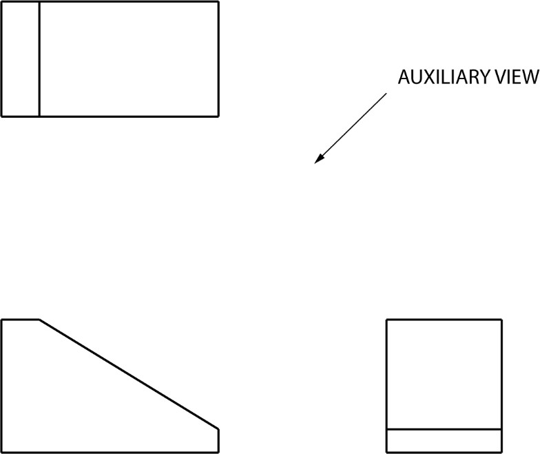
Determing Which Side to Use for Auxilary View
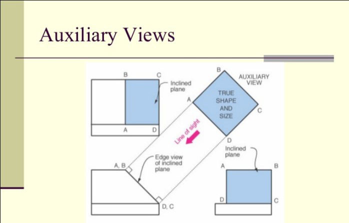
Therefore when front rear or side auxiliary views are desired the reference plane. A view direction perpendicular to the edge view of a plane will always reveal the true shape and size of features on a plane.
Drafting Auxiliary Views Britannica
A primary auxiliary view is a single view projected from one of the six principal views.
. Create an auxiliary view from orthographic views. An auxiliary view that is hinged on the top view is a top auxiliary view as shown in Figure 9-5B. When the marquee encloses the view release the mouse button.
After reading this chapter you will be able to. You can create an auxiliary view of an exploded assembly view. The auxiliary view appears in the upper right corner of the 2-D ORTHOGRAPHIC window.
An Auxiliary View is similar to a Projected View but it is unfolded normal to a reference edge in an existing view. In this example a front and a right-side view were drawn. In this example to properly orient the auxiliary view add a perpendicular relation between the sketched line.
The original three views reappear. Finally a view hinged on the right-side view is a right-side auxiliary view. The groove in surface ABCD makes an angle of 30 with a line not shown parallel to the edge DC.
Draw primary auxiliary views representing the true shapes of surfaces that are perpendicular to one of the reference planes and inclined to the other two. Of the principal planes of projection and is inclined to the other two. This exercise takes you through the steps required to construct an auxiliary view.
This is the line of sight. A tertiary auxiliary view is a single view projected from a secondary or another. The auxiliary plan view is a true view on the tilted box.
The reference plane top view represents an edge view of the orthographic view front view from which the auxiliary view will be projected. Click the View Layout tab. If a view is now taken in the direction of arrow Y the tilted box will be turned through 90 in the direction of the arrow and dimension 1 to the corner will lie parallel with the plane of the paper.
A left side auxiliary view is needed. The primary reference of the top auxiliary view is the height of the object. Because there is only one auxiliary view and its origin is obvious no defining cutting plane line is needed.
You can use sketched lines for folding. Draw apparent shapes of surfaces in either the principal views or auxiliary views if at least one of the views represents the. Drawing the marquee around the auxiliary view.
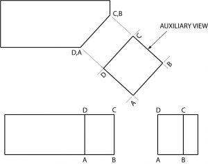
A primary auxiliary view is projected onto a plane that is perpendicular to one. Find the line that is considered the edge view of the inclined plane. Where auxiliary view will be drawn Construction lines are reference lines parallel to angled edge Edge View of Reference Plane Creating Auxiliary Views Step 3 Draw construction lines outward from each corner of view Auxiliary view will be a 90 rotation of view Lines must be perpendicular to angled edge.
Direction for the frontal and profile planes is horizontal and the view direction for the horizontal plane is vertical. Construct the development of prisms pyramids cylinders and cones. Its primary reference is the width of the object see Figure 9-5C.
An auxiliary view in which A B C and D are labeled with primes obtained by projection onto a plane P parallel to the surface ABCD is the only one in which the true shape of ABCD and the true size of the 30 angle are correctly shown. Move the pointer above the view you want to select. It is angled to the horizontal top and profile side viewing planes.
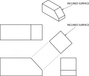
If the auxiliary view lies uniformly on both sides of the reference line then it is called Symmetrical Auxiliary Views. I have given you 3 views in 1st angle orthographic projection conventional - front left and plan and ask. Examine the views that are given for an inclined surface.
Hold the left mouse button and drag the marquee around the view. While if it lies on one side only of the reference line then it is called Unilateral Auxiliary Views. Line AB actually represents an edge view of surface ABE.
Up to 5 cash back Construct partial auxiliary views. To see the true shape and size on an inclined or oblique face an auxiliary view must be created. You will need your textbook worksheet for this exercise.
The auxiliary plane is drawn parallel to line AB in the front view. A secondary auxiliary view is a single view projected from a primary auxiliary view. Click the arrow box in the Auxiliary View manager box.
I Redraw the given views and divide the circles in the auxiliary view in 12 parts and number 2 These points transferred to front view and then horizontally towards side view as shown in Fig. Produce views to show the true length of a line point view of a line edge view of a surface and true-size view of a surface. 3 Since the auxiliary view is symmetrical about PQ.
In the front view draw a light construction line at right angles to the inclined surface. It is possible to create any number of auxiliary views including a new auxiliary view from an existing auxiliary view. Show the true size of the angle between two planes dihedral angle.
Up to 5 cash back OBJECTIVES. If the auxiliary view lies uniformly on each side of the reference line then its reffered to as Symmetrical Auxiliary. How to find the true shape of a surface using an auxiliary plan.
Select a location for the auxiliary view and click the mouse. If the auxiliary view does not uniformly lie on both sides of the reference line then it is called Bilateral Auxiliary Views. Create auxiliary section views.
Hi everyoneThis question will be posted to Sakai.
Auxiliary Views Basic Blueprint Reading
Auxiliary View Its Types Methods A Comprehensive Guide
Auxiliary Views Basic Blueprint Reading
Auxiliary Views Basic Blueprint Reading


Comments
Post a Comment